Ad blocker detected: Our website is made possible by displaying online advertisements to our visitors. Please consider supporting us by disabling your ad blocker on our website.
I bought another 2x256Mb memories in eBay (UK), just got them and it works ! my 600E now has 512Mb RAM (question, why the base 32Mb seems to have dissapeared when I installed the new ones?)
Finally I have my 600E upgraded (I'll not do the step.... hardware upgrade) and I only have to change the display cable I broke when I dissasembled first time the laptop.
Thanks to every one that helped... and kind regards to all....
and are made by 8 small chips per side (that makes 16 small chips per 256Mb memory) branded:
SAMSUNG 151
K4S280832C-NL1L
I also disabled the "paging executive" and defined "LargesystemCache" at "1" following recommendation I read in another forum (thinkpads)
BTW, my 600E is a 2645-550, one of the older ones and less probable to be able to upgrade !!!
The only problem I still have is that I have to manually enable the processor L2 cache, because PowerLeap CPU ControPanel gives error "unable to load ring0...." either if started with the "Automatically start at startup" or putting it in Init set pf programs to start at startup. And the other utility suggested in another forum "cacheutility" gave a BSOD when I tried it time ago.
Any idea to solve this problem? And any idea about why the 32MB base memory dissapeared?
fje; manually enable the processor L2 cache, because PowerLeap CPU ControPanel gives error "unable to load ring0...." either if started with the "Automatically start at startup" or putting it in Init set pf programs to start at startup.
To configure PowerLeap CPU Control Panel Version 5.1- The only box i have checkmarked is - Automatically start at startup.
The Force L2 Cache to enable- (and all other boxes) remain unchecked.
PL 5.1 works perfect this way. It auto enables L2 cache and sets the cpu to full speed. For a while (my 4AU) was not starting at full speed so i ran the DeepSleep program once and PL 5.1 is again flawless.
I tried to re-configure PowerLeap CCP. I unchecked the L2 Cache force enable and checked the "start at startup"
Now, when booting it seems the "unable to load ring0...." is not there, but the L2 Cache remains disabled, and we are loosing one of the Pentium III "goodies".
So, I feel I have to stay with manual start and enabling the L2 cache. Any idea about how to avoid the startup ring0 error?
fje: Your PL issue is mentioned on page 47 of this thread. I think i had the same error you mention (it was over a year ago). If my memory is correct, i think i got the error corrected by unzipping PL files with 7zip. The first time i tried PL it gave me problems. After searching this thread i noticed others were having trouble with PL so i redownloaded the PL file and unzipped it using 3 different programs before i got it right.
The DeepSleep utility mentioned on this thread can cycle PL as well. (V1.3)
SqueakyPC wrote:fje: Your PL issue is mentioned on page 47 of this thread. I think i had the same error you mention (it was over a year ago). If my memory is correct, i think i got the error corrected by unzipping PL files with 7zip. The first time i tried PL it gave me problems. After searching this thread i noticed others were having trouble with PL so i redownloaded the PL file and unzipped it using 3 different programs before i got it right.
The DeepSleep utility mentioned on this thread can cycle PL as well. (V1.3)
SqueakyPC, thanks, I was already aware of the posts in page 47 you refer to. For this reason I tried both possibilities, mark "start at startup" and put in the "init" set of programs to start, and both gave me the error. This is the reason I asked again for it, and the same is valid for the BSOD of the cacheutility....
I looked these up, they seem to be custom made for the Panasonic Toughbook. Not sure how compatible they are with other systems, and at almost $150 a piece it's not worth the risk
At the risk of being OT I wanted to update everyone on the memory slot problem I had with my prized 810 Mhz 107 fsb 534 Mb TP600E.
As you may recall, one of the memory slots gave out, and I also cracked the screen.
I decided to get another TP600E on Ebay, and possibly trade parts. Unfortunately the one I bought ALSO turned out to have a bad memory slot. So I then had two with the same problem.
I lived with 256 megs max ram for awhile, and finally decided to spring for a later model Thinkpad, a T30.
Imagine my surprise when THIS TOO had a bad memory slot. However, it was sold as a 512 Mb computer -- it actually had two 512 Mb memorys installed, and therefore fit the advertised memory size.
I did a little research at this point about T30 memory problems, and Lo and behold, it turned out to be a common problem, and even resulted in free replacement motherboards from IBM for a limited time.
What happens is, the solder joints on the memory clip gradually flex and crack.
I wondered if this same thing had happened to the TP600Es.
I also read that a few individuals had actually re-soldered the 200 pins on the T30, and restored their memory slots. This seemed fantastically hard to do, and I thought about it for a short time, but never did anything.
This week my T30 crashed, and guess what? The other memory slot had gone bad. I was able to place some folded pieces of paper under the memory cover to press against the memory card, and boot up properly. This confirmed the cracked solder joint problem.
So I took courage and went to Radio Shack and bought a tin of solder flux, an inexpensive dual heat soldering iron and station, and a set of two large chisel tips to fit that. I also bought a magnifying glass circuit holder stand. The total was still under $50.
I decided to have a go at the TP600Es first, in case their problems were due to cracked joints as well. That would be good practice for the T30 with its even finer contacts.
I used a portable book light to focus light on the card slot connectors. Peering through the magnifier, I took a strand of wire wrap wire and dipped it into the flux and using it like a tiny paintbrush, painted the contacts with flux.
Then I used the soldering iron at 25 watts to press for a few seconds against 4 or 5 of the PC pads at once. I added NO solder, just remelted what was there with the new flux. The iron tip had been tinned and carefully wiped off. I didn't want any solder bridges from excess solder. Working with a group of contacts at a time I worked my way across the connectors, then turned the computer around and did the same for the backside contacts of the connector.
Crossing my fingers, I slipped one memory card into the known bad slot, buttoned up the computer and replaced the battery pack. I flipped it over and WOW! IT WORKED. My first TP600e was back in business with 2 working memory slots.
I worked on the other TP600e and finally the two slots in the T30. All were restored to full function! True, I had to redo a connector a couple times -- it's hard to tell if you re-melted every contact sometime. But ultimately all worked! I was very careful to inspect for solder bridges before testing the chips. The few I noticed responded to simple re-heating with the iron.
So there you have it -- 600e memory repair. I've never heard of it being done with them -- just the T30. If my experience is any indicator, others may find the same problem cropping up. Hope this helps them, as well.
Thanks once again Sharedoc, let's keep these 6ooe's going!
ps.
Oh, the end of the story -- what happened to my TP6ooE with the cracked screen?
Well, I installed Puppy Linux 4.1.2 retro on it, with a new 80Gb hard drive, hooked it up a network card, installed TightVNC, samba server, and set up an ftp server as well. It's now a headless (well cracked-headed) file server for backup and downloads.
It's great -- low power draw, it's always on, and in our latest power outage here (due to the worst ice storm ever), it acted like a UPS, as well, since it had a battery. It went for nearly 2 hours (since there was no screen display to draw current). It has breezed through shorter power outages without stopping,
Eventually it shut itself down after the big one, in such an orderly fashion (suspend) that when the power was restored, it was up again on its own with a touch of the power switch, not rebooting, but simply resuming from where it was.
I can still read the cracked screen if necessary, but I don't need to with TightVNC. I just bring it's screen up on my other computer's when needed.
It is great for long overnight downloads, and allows other computers to be shut down. I will be connecting a USB DVD burner and will make it a central station for this in the house. All in all, not bad for a "broken" "unsupported" "outdated" computer.
TP600Es never die. They just do more than intended when built.
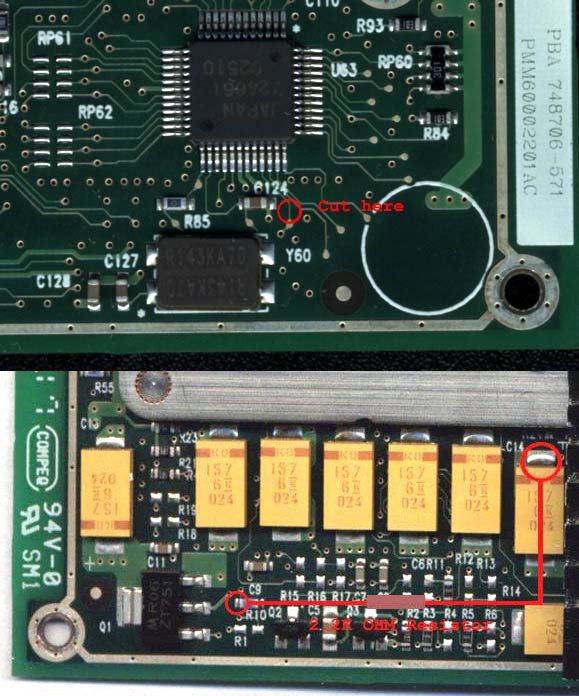
The original sketch of the Sharedoc mod shows the 2.2Kohm resistor soldered at condenser C13 to resistor C9
(quote from pg. 3):
On the top level of the board this pass through meets a resistor, south from text C9. Solder to the west end of this resistor
a 2.2kohm resistor, and solder the other end of the resistor to north end of condenser C13. C13 is to west-north from text C9. http://www.wimsbios.com/phpBB2/topic4046-30.html
(quote from bottom of page 39):
I realized that there is an inconsistency between what Sharedoc suggests for the TP 600E upgrade and the picture
I’ve found in this thread. I wonder if I soldered the 2k2 resistor to the wrong end.
In Sharedoc’s drawing it seems to be C13, but according to the picture (photo) I’ve found in the forum,
the resistor seems supposed to be soldered to C14. I used C13 which is located on the right side of C14. http://www.wimsbios.com/phpBB2/topic4046-570.html
In the picture entitled "My 700MMC-2". From left to right there is a row of 7 condensers then a space then one more condenser:
Which condenser should the 2.2Kohm resistor be soldered to?
Oh, also, for those who might still consider doing the speedstep hardware mod, there is an error in the instructions on page 3 of this thread where it says:
"On the top level of the board this pass through meets a resistor, south from text C9. Solder to the west end of this resistor a 2.2kohm resistor, and solder the other end of the resistor to north end of condenser C13. C13 is to west-north from text C9."
The last sentence (bolded portion) is incorrect, and caused me a fair amount of confusion, since there are caps in that general area, but the silkscreened cap legend is hidden by a plate -- one almost looks like C13 but the last digit is partially obscured.
In fact C13 is located above and far to the right (East Northeast) of a horizontal bank of caps. It has a legend (C13) if you know where to look. It is convenient to bring a resistor to this point because the leads are reasonable length.
There are drawings 2 posts later by Pkiff. Drawing 1B shows the C13 mod correctly with the resistor leads long and the cap above and a long way to the right of the first resistor solder point.
The first 600E i modded went perfectly.
The Speedstep mod, and the 108Fsb mod went well,
Powerleap and DeepSleep installed without any real problem. Roughly one in twenty startups results in the 108 stop code. On the second 600E i was not so lucky. During the 108Fsb Mod the soldering tip stuck to the SM resistor and it was accidentally pulled off of the motherboard. When i tried to re-solder the SM resistor, the tip stuck again and i accidentally lifted the trace off of the mother board. I have a spare mother board but this one i damaged may still work. One of the solder pads that the SM resistor resides on was in tact, so onto that pad i soldered a 1/8 watt, 10Kohm resistor. To the other end of this (10K) resistor i soldered the damaged trace AND one end of the 1Kohm Fsb Mod resistor. After the final connection beside C21 it is time for the Speedstep mod. If there is anyone who is interested in knowing how much damage can be done to an MMC-2 processor...

